How Boeing 747 systems work together
Follow useful power from its source to its consumer, distinguishing energy, commands and indications. Backup systems also have dependencies that determine what remains available.
A 747's systems are often described in separate chapters: electrical, hydraulic, pneumatic, fuel and environmental control. The aircraft itself does not respect those chapter boundaries. One system supplies energy to another, a third controls the connection, and the flight deck presents the result.
A useful way to understand the aircraft is to ask four questions about each function: Where does its energy come from? How does that energy reach it? What commands it? What remains if one part is unavailable?
Start with three forms of useful power
An operating engine provides more than propulsive thrust. Its mechanical drive can power accessories, while compressor air can supply pneumatic consumers. Electrical generation and hydraulic pumping convert some of that mechanical power into other useful forms.
| Power path | Conversion | Example of the eventual job |
|---|---|---|
| Engine shaft → generator → electrical buses | Mechanical energy becomes electrical energy | Supplying instruments, computers and electric motors |
| Engine shaft → hydraulic pump → actuator | Mechanical energy becomes fluid power and then motion | Moving powered flight-control surfaces |
| Compressor air → pneumatic duct → pack | Compressed air provides the supply and energy for conditioning | Producing conditioned outside air for the cabin |
| Compressed air → air-driven hydraulic pump, where fitted | Air power becomes hydraulic power | Providing an alternative drive for a hydraulic circuit |
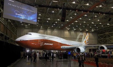
These are simplified functional paths, not a plumbing or wiring diagram for one aircraft. Boeing's 747-8 power-on report describes the electrical, hydraulic and pneumatic systems being brought into operation as distinct but related services.
A command is not the same as the power to carry it out
Consider a valve in an air duct. The valve carries compressed air, but its command or position indication may depend on electricity. Likewise, a flight-control actuator may use hydraulic pressure while a separate control path tells it how far to move.
This is why "electrical fault," "hydraulic fault" and "control fault" are not synonyms. A powered actuator can still lack a valid command. A valid command cannot move an actuator that lacks the required power. An indication can also fail without the underlying mechanism failing in exactly the same way.
The electrical article explains source and bus isolation. The hydraulic article separates pump drive, fluid quantity and actuator power. Reading them together reveals why a single cockpit message rarely tells the whole physical story.
Follow cabin air across three systems
First, the pneumatic system supplies compressed air. Next, the packs condition it for distribution. Finally, cabin pressure control regulates outflow while taking account of the available supply and the pressure environment.
A temperature problem can originate in conditioning or distribution. A pressure problem can involve inflow, outflow control or leakage. The aircraft therefore needs more than a single "cabin air working" indicator.
The bleed-air guide follows the source and ducts; pressurisation and air conditioning follows conditioning, recirculation, outflow and the pressure vessel. The FAA's airframe handbook provides the underlying electrical, fluid-power and environmental-control principles in chapters 9, 12 and 16.
What does losing one engine actually remove?
It can remove more than thrust: the associated accessory drives and air source may also be affected. But losing a source is not automatically the same as losing every system that normally uses it. Alternate supply paths and backup drives can preserve some functions.
The outcome depends on which physical parts remain intact. A stopped pump with a healthy circuit presents a different problem from a leaking circuit. A disconnected generator presents a different problem from a shorted bus. An unavailable air source presents a different problem from a ruptured duct.
This is the practical reason to distinguish source failure, distribution failure and consumer failure. Each affects a different portion of the chain, and each leaves a different set of useful alternatives.
Redundancy has dependencies of its own
An electrically driven backup pump still needs electrical power. An air-driven backup pump still needs a suitable air supply. Two devices that share an essential connection are not fully independent merely because they have separate names on a panel.
Physical hazards matter too. Separate circuits can be exposed to the same damaged structure, heat source or equipment compartment. The FAA's JAL 123 case study illustrates why considering common-cause damage is essential when discussing redundant systems.
None of this makes redundancy pointless. It explains what a careful account of redundancy must include: the number of channels, their distribution, their support requirements and the events that could affect more than one channel together.
Choose a reading route
- To understand how things move: start with hydraulics, then flight controls and landing gear.
- To understand how equipment stays powered: start with electrical distribution, then the APU and flight-deck indications.
- To understand the cabin environment: start with bleed air, then pressurisation and oxygen.
The articles identify their variant scope and distinguish general engineering principles from aircraft-specific details. They explain architecture; they are not operating checklists or maintenance instructions.
Sources
Facts on this page are checked against the primary and institutional references below.
Related topics
Compare aircraft sizes
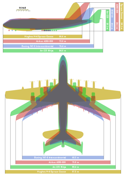
Compare Boeing 747 variants, the Airbus A380 and Boeing 777 on one scale. Overlay their dimensions, switch views and see lengths and wingspans.
Boeing 747: History, Variants and Legacy
A complete reference to the Boeing 747, built from 1968 to 2023 - every variant from the 747-100 to the 747-8, plus special-mission jumbos and photos.
Listen to Boeing 747 engines
Listen to licensed Boeing 747 recordings, compare RB211 and GEnx-2B engines, filter by flight phase and download credited audio clips.
Explore the Boeing 747
Design a 747 livery, load a freighter, explore cockpit instruments, find flights and spotting locations, hear engines and share aircraft memories.
Boeing 747 Family
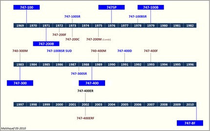
Every Boeing 747 variant built between 1968 and 2023 - the 747-100, -200, -300, -400 and 747-8, with freighter, combi and short-range models explained.
Boeing 747 Production Data
Download Boeing 747 production totals by generation, with a transparent method and links to Boeing's final programme record and technical documents.
More in Aircraft Systems
How the 747 works
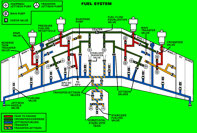
The systems that make a 747 fly - fuel, hydraulics, landing gear, electrics and pressurisation, explained one at a time.
Boeing 747 specifications compared
Compare Boeing 747 dimensions, performance and detailed later-variant weights, fuel and cargo capacities, with Boeing planning configurations identified.
Boeing 747 Freighter Specifications
Compare Boeing 747-400F, 747-400ERF and 747-8F weights, structural payload, fuel and cargo volumes using identified Boeing planning configurations.
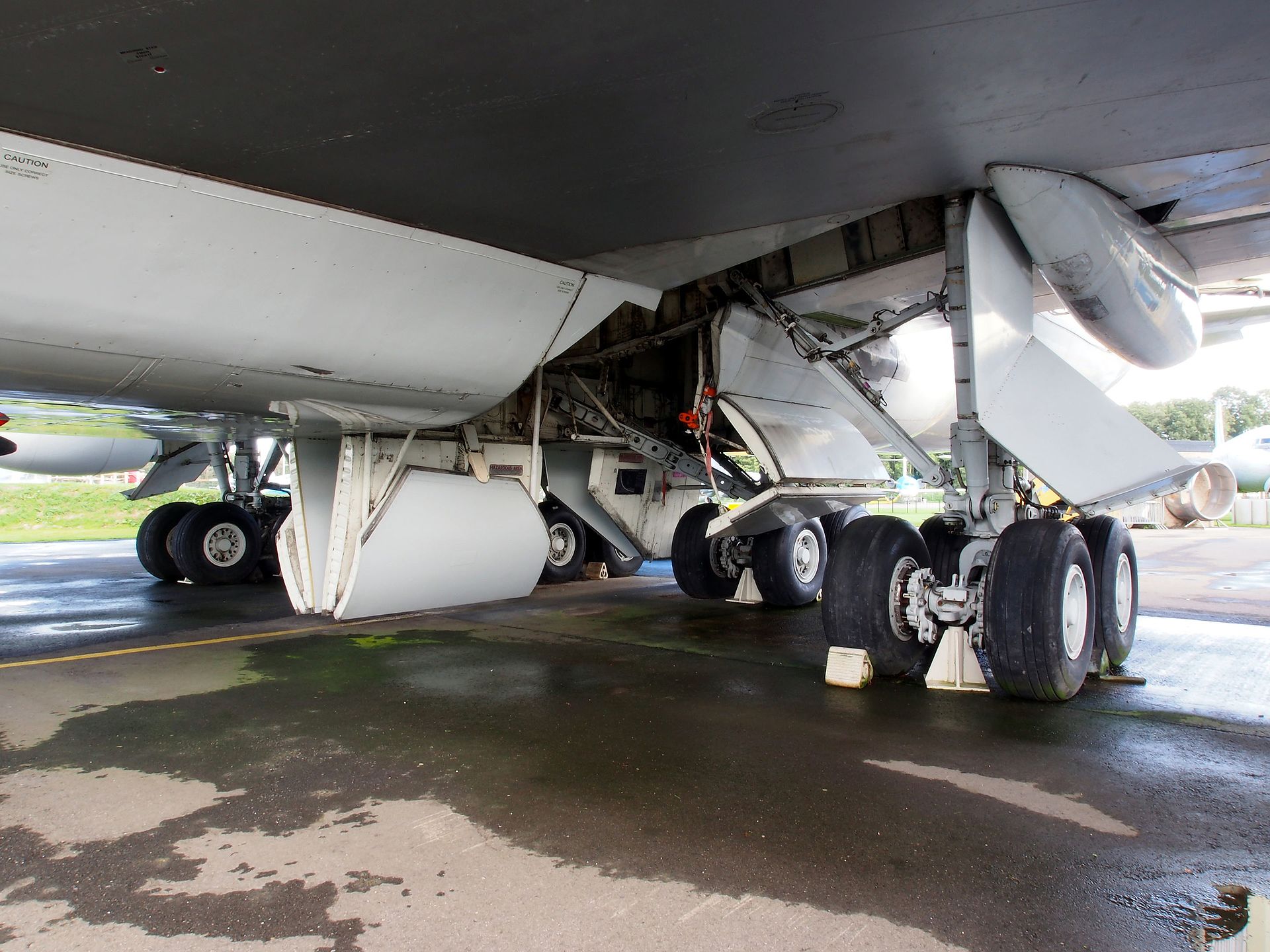
How the 747 hydraulic systems work
Follow the 747's four hydraulic circuits through pumps, actuators and return lines, and understand pressure, flow, backup drives and common-cause damage.
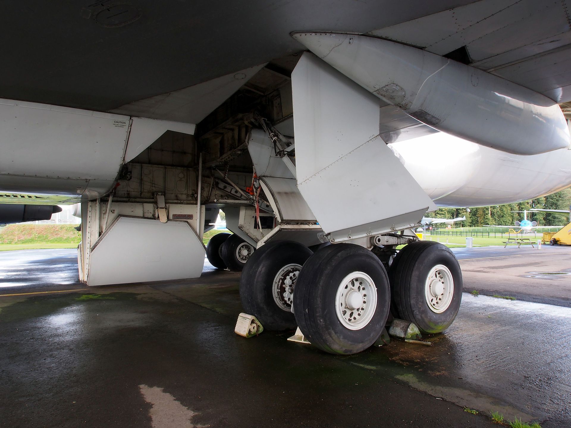
Landing gear, steering and ground loads
Explore the Boeing 747 landing gear: eighteen wheels, shock struts, retraction, body-gear steering and the forces transmitted to the runway.
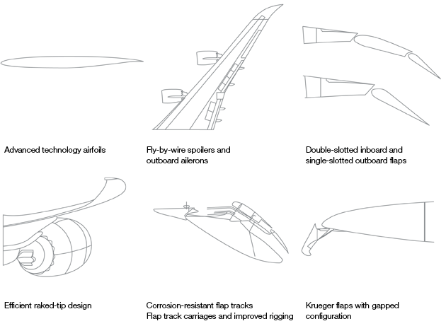
Flight controls and high-lift devices
Explore Boeing 747 flight controls, hydraulic actuation, flaps, spoilers and trim, with an illustrated guide to the changes on the 747-8.